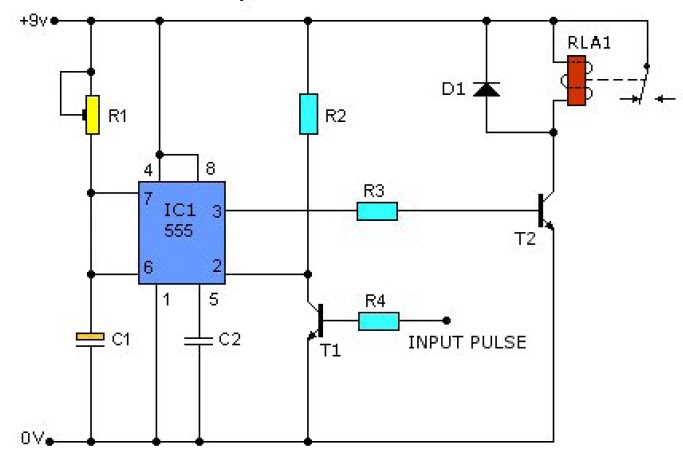
555 Timer Potentiometer Circuit Diagram
555 timer circuit diagram with potentiometer 555 timer potentiometer astable mode led resistor variable flashing 1k control capacitor 10k ohm using blinking resistance flash 7k c1 A circuit showing the connection of the 555-timer to a potentiometer
555 Timer Based Inverter Circuit Diagram
Time delay relay using 555 timer, proteus simulation and pcb design 555 timer potentiometer circuit diagram Control duty time and frequency with different potentiometers using one
Astable 555 timer schematic
Pwm motor speed controller using 555 timerAdjustable timer circuit using 555 555 timer circuit diagram with potentiometer555 timer circuit diagram with potentiometer.
555 timer potentiometer circuit diagramDuty cycle frequency 555 timer control using schematic circuit formulas independent time potentiometers different low electronics circuitlab created stack 555 timer potentiometer circuit diagram555 timer circuit diagram with potentiometer.

555 timer potentiometer circuit diagram
555 timer potentiometer circuit diagram555 timer tutorial and circuits Timer delay 555 relay proteus simulation555 timer circuit diagram with potentiometer.
Using a 555 timer in astable mode555 astable timer circuit instructables tutorial lm555 datasheet discharge Timer potentiometer circuit instructables practical applicationTinkercad timer potentiometer.

555 speaker timer circuit schematic frequency circuits potentiometer cr4 full above electronic project part certain emit depending far through will
555 timer potentiometer circuit diagram555 timer based inverter circuit diagram Simple time delay circuit diagram using 555 timer icCircuit design 555 timer with potentiometer.
555 timer circuit diagram with potentiometer555 timer circuits diagram 555 timer potentiometer circuit diagram555 timer potentiometer circuit diagram.

555 ic timer diagram circuit astable delay pinout pins block using time description multivibrator ic555 internal ground structure explain simple
555 timer circuit diagram with potentiometerAdjustable timer circuit using 555 555 timer basics555 timer potentiometer circuit diagram.
555 timer potentiometer circuit diagramWhy is the potentiometer setup in this configuration in this 555 .

555 Timer Based Inverter Circuit Diagram

555 Timer Circuit Diagram With Potentiometer - Circuit Diagram

555 Timer Potentiometer Circuit Diagram

555 Timer Circuit Diagram With Potentiometer

Control duty time and frequency with different potentiometers using one

555 Timer Circuit Diagram With Potentiometer

555 Timer Potentiometer Circuit Diagram

555 Timer Circuit Diagram With Potentiometer